On-Board Diagnostic – Monitoring & Readiness Monitors

The primary purpose of the PCM, ECU, ECM, ... is to manage automobile resources to ensure the emissions from the car meet emission standards at time of sale. It manages automobile resources such as injectors, engine timing, EGR, … in regards to controlling them and ensuring they are operating effectively so that the overall system can maintain the emission's standard.

The PCM utilizes monitors to ensure components and engine are working within the OBD II specifications. For example, the PCM constantly monitors for misfires. Likewise, when certain conditions are met, the catalytic converter(s) is/are tested to ensure proper behavior.

Why should you be aware of Readiness Monitors

As for me, I live in California. Yup! Hot Rodder hell. So, in California, being CARB legal is a big deal. Since Check Engine Light issue must be resolved in CA to pass smog tests or resell a vehicle, I have helped many people resolve them. Therefore, if you live in a state where you must periodically smog test your vehicles, than knowing about Readiness Monitors can be helpful, especially if you are a car flipper.

For an automobile to pass a smog test, the following conditions must be met:

The following explanation of Monitoring is simplified due to the following:

Readiness Monitors Overview

The following table summarizes some of these potential monitors for a gasoline engine automobile:

<Toggle Table Display>
Monitor Name Description When Executed
Continuously Driving condition is met
Misfire
Purpose
This monitor ensures each cylinder is contributing to rotating the crankshaft evenly. Each time a spark plug fires, a certain valid range of angular velocity should be produced. Issues with compression, fuel delivery, and/or ignition can cause one or more cylinder misfire(s). Unfortunately, problems with these systems can either cause damage to other emissions related equipment or can produce excessive emissions. For example, a stuck open fuel injector can cause excessive fuel to enter the catalytic convertor, damaging it.
General Algorithm - <read more...>
The PCM utilizes readings from the crankshaft position sensor, camshaft position sensor, engine speed sensor, and/or catalytic converter temperature sensor are used by algorithms to determine if one or more cylinders are producing expected power. For example, if a cylinder’s sparkplug fires and the camshaft position sensor does not produce the appropriate number of pulses in a given time interval based on the current RPM, this would indicate that cylinder did not produce the expected power, indicating an issue. From my experience, you can rely on misfires telling you of an issue, but many PCM algorithms have a hard time determining the true faulty cylinder.
Fuel System
Purpose
This monitor ensures that the fuel system is behaving as the PCM expects so that necessary emission standards can be achieved.
General Algorithm - <read more...>
In automobiles levering an upstream O2 sensor, this monitor utilizes an algorithm to ensure that the Short Term Fuel Trim can cause the O2 signal to cycling around the 14.7:1 threshold as expected for the current operating conditions. In automobiles levering an upstream Air/Fuel sensor, this monitor utilizes an algorithm to ensure that the Short Term Fuel Trim can cause produce the appropriate A/F ratio within a certain threshold of time for a given engine load. If the appropriate results of these tests fall into acceptable ranges, the fuel system is considered to be in good operating health.
Comprehensive Component
Purpose
Since for the PCM must be able to sense and control components of the engine, this monitor ensures all important components are responding.
General Algorithm - <read more...>
This monitor leverages algorithms that ensure all sensor readings are within range and change as expected. In addition, sensor readings are used to determine if other sensor readings make sense. Many times techniques as circuit biasing and voltage sensing are used to ensure important circuits are not open or shorted.
Catalyst
Purpose
Since catalytic converters leverage a heated chemical reaction on the engine’s exhaust gas to reduce harmful emissions, all catalytic converters need to be functioning. This monitor ensures that the catalytic converters are functioning as expected.
General Algorithm - <read more...>
1996 and newer cars have either an O2 sensor or an Air/Fuel sensor before the catalytic convertor(s), closest to the engine, and another O2 sensor after the catalytic converter. When all A/F and/or O2 sensors are at operating temperature and an extended cruise is occurring, this monitor utilizes an algorithm to compare the upstream sensor output to the downstream sensor output. In addition, sometimes the catalytic converters will be outfitted with temperature sensors. A properly functioning catalytic converter will cause the upstream and downstream sensors to differ in the readings, mainly the downstream sensor should be less reactive and should be leaner in certain situations. If temperature sensor(s) are used, they should indicate that the output gas temperature of the catalytic converter is hotter than the input gas temperature.
Heated Catalyst
Purpose
Since catalytic converters leverage a heated chemical reaction on the engine’s exhaust gas to reduce harmful emissions, the quicker the catalytic converters warm up the quicker the chemical can occur to reduce emission during automobile warm-up. Therefore, in an effort to reduce warm-up emissions, many manufactures leverage catalytic converter heaters.
General Algorithm - <read more...>
This monitor ensures the heater circuit is functioning and that the catalytic converter(s) start functioning within a specific time period. The upstream Air/Fuel or upstream O2 sensor(s), which have heaters as well, and downstream O2 sensor(s), which have heaters as well, and sometimes, if equipped, temperature sensors are used to determine if the catalytic converters warm up within a time frame specification.
Evaporative System
Purpose
When the automobile is being refueled, gas is being pumped through the fuel system, and as the gas tank is being moved causing the gasoline to slosh around, fuel vapors are being created. These vapors are harmful to the environment. Therefore, the Evaporative System’s, commonly referred to as EVAP, responsibility is to capture and then burn in the engine when appropriate.
General Algorithm - <read more...>
The EVAP system usually is made up of two solenoids and a pressure sensor. One solenoid is located on the intake to meter vapors being released into the intake manifold. The other solenoid is located by the gas tank. Generally, these two solenoids are connected via tubing with a pressure sensor attached. Therefore, when conditions are right, the algorithm closes both solenoids trapping engine vacuum in the tubing connecting the fuel tank to the intake. For a specific time period, only so much vacuum can bleed off. If too much vacuum is lost for a given time interval, the system is considered to have an unacceptable leak.
Secondary Air System
Purpose
Larger displacement engines produce a fair amount of exhaust gases that need to be cleaned/processed by the catalytic converter. Catalytic converter can only handle so much gas at a time. So, in some vehicles they employ numerous converters or use air pumps to increase the temperature of the converter.
General Algorithm - <read more...>
Due to numerous system configurations, there are a variety of ways this system can be verified. The following is an example of such an algorithm. Once all of the necessary conditions are met, the PCM leverages an algorithm that will turn on appropriate check valves, allowing outside air to be added to the exhaust system. The test will be considered successful if either the O2 sensor indicates a lean condition and/or catalytic converter temperature increases appropriately.
Oxygen (O2) System
Purpose
Air/Fuel and O2 sensors are leveraged by automobiles to track the oxygen content of the exhaust stream and the catalytic converter efficiency. Air/Fuel, wide band, sensors, tend to be held at a constant ratio by the PCM. Whereas, O2, narrow band, sensors are alternated around the 14.7:1, Stoichiometric ratio, by the PCM. Both Air/Fuel and O2 sensors are only able to properly sense the oxygen content when the sensor is warmed up to around 600 degrees.
General Algorithm - <read more...>
Once the driving conditions are appropriate and the Air/Fuel and/or O2 sensors are warmed up, the PCM will make well known changes to the injector duty cycle. This should result in the exhaust stream to either be expectedly lean or rich. If the sensors react within a certain time period and give the appropriate results, the test is considered successful.
Oxygen Sensor Heater
Purpose
Air/Fuel and O2 sensors are leveraged by automobiles to track the oxygen content of the exhaust stream and the catalytic converter efficiency. Both Air/Fuel and O2 sensors are only able to properly sense the oxygen content when the sensor is warmed up to around 600 degrees.
General Algorithm - <read more...>
Once the driving conditions are appropriate and the Air/Fuel and/or O2 sensors are being warmed up from a cold state, the PCM will ensure that these sensors start to produce results within a certain time interval.
EGR - Exhaust Gas Recirculation
Purpose
As the engine runs, the combustion chamber temperature rises above 2,500 degrees. At these temperatures, nitrogen oxide is created which is bad for the environment. Under certain driving conditions, e.g. light acceleration, the Exhaust Gas Recirculation System, EGR, redirects exhaust has back into the intake manifold, resulting the combustion chamber temperatures to decrease.
General Algorithm - <read more...>
Once the driving conditions are met, the PCM will leverage an algorithm that can leverage one or more of the following sensors and expected results:
  • Manifold Absolute Pressure(MAP) sensor – sense a decrease in intake vacuum
  • O2 sensors and/or Air/Fuel sensors – sense leaner exhaust gas
  • Catalytic converter temperature sensor – sense a cooler exhaust gas temperature

Note: These monitors are cleared if the battery is disconnected or a scan tool clears them.

Readiness Monitor Drive Cycle

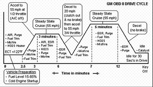
After reading the above table, you probably noticed that many of the readiness tests require a certain condition to be met to allow them to complete successfully. But what does a drive cycle look like? Here is an example drive cycle for a GM. I pulled it from the Autozone.com web site.

Drive Cycle Example

To find your car’s specific readiness monitor drive cycle, please consult your shop manual. If you don't have a shop manual, you can utilize Mitchell DIY Online to allow you to access a digital shop manual. From experience, follow them to the letter; otherwise, many times the readiness monitor won't complete successfully or even initiate.


Related Links

Related Videos